
Why environmental stress should come before purchase price
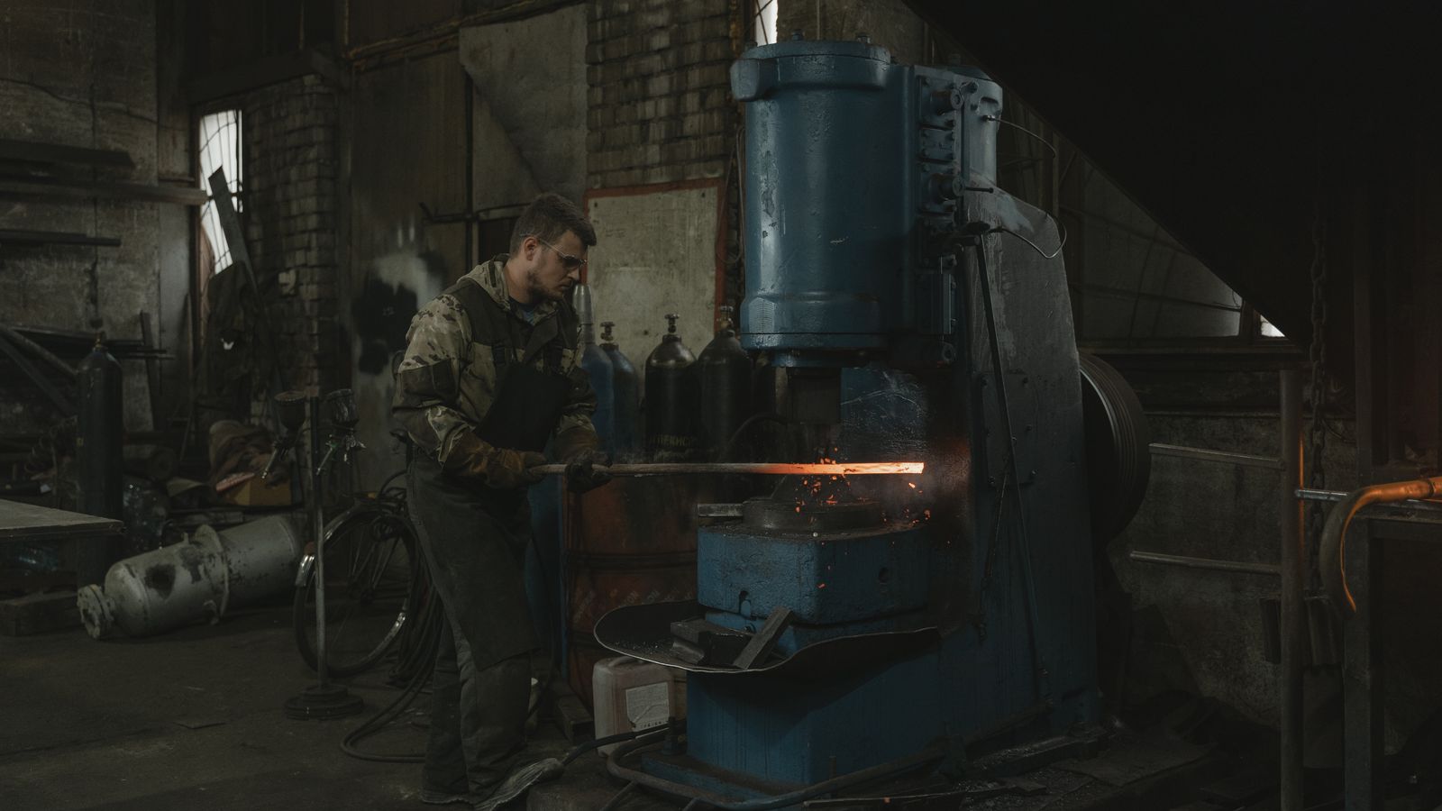
In hot, dusty locations such as steelworks, foundries and forging shops, and areas around heat-treatment furnaces, it is difficult to compare instrumentation costs from price tags alone. Even identical gas detectors or temperature and humidity transmitters can have very different operating lives depending on radiant heat, the rate of temperature change, moisture condensation, iron-oxide dust, oil mist, cleaning agents, and process gases at the installation point. If protective components clog frequently, workers must enter the area to replace them; if sensor drift accelerates, calibration and spare-parts management also increase. When delayed alarms or missing data force a process shutdown, the operational burden can far exceed the equipment purchase price.
Total cost is therefore not merely the sum of the instrument, sensor, and installation work. It must also include filters and calibration gas consumed over the service period, inspection labor, work permits and personal protective equipment for safe access, spare instruments, data gaps, troubleshooting, sensor and pump replacement, and planned and unplanned downtime. The starting point for reducing cost is not choosing the cheapest sensor, but first designing the path by which heat and dust can reach the signal.
Temperature creates different costs for sensors and electronics
In a gas sensor, temperature can change the rates of chemical reaction and diffusion, catalytic activity, and electrical output. Even with temperature compensation, the sensor and surrounding air need time to reach thermal equilibrium after a rapid move or immediately following a process transition. NIOSH explains that field-calibration conditions should match actual use conditions as closely as possible and that sufficient equilibration time is especially important because temperature changes can introduce measurement bias. OSHA likewise advises that environmental conditions such as temperature and humidity affect sensor response and that testing and calibration should be performed under conditions similar to the actual workplace.
A sensor’s ability to withstand a high-temperature process does not mean that the transmitter electronics, battery, display, and cable glands permit the same temperature. The manufacturer’s operating ranges for the sensor and instrument body must be checked separately. A separated installation may be more stable: a high-temperature probe measures inside the process while the electronics are moved behind a heat shield or into a cooled area. Remote installation, however, adds cables, junction boxes, tubing, supports, and inspection access routes. Even if initial construction cost rises, lifecycle cost may fall if the arrangement reduces electronics degradation, repeated replacement, and entries into the hot zone.
Radiant heat is also easy to overlook. Even when ambient air temperature is within specification, direct heating of a sensor housing by molten metal, a furnace wall, or a hot duct can raise its internal temperature further. An installation review should record worst-case surface temperatures, the direction of radiant heat, temperature changes during process startup and shutdown, and cooling after washing rather than relying on average air temperature. Heat shields and separation distances must be selected without preventing the gas being measured from actually reaching the sensor.
Humidity and condensation create recovery time as well as error
In humidity measurement, even a small temperature difference between the sensor and the air can become a significant relative-humidity error. Vaisala technical literature explains that a temperature difference causes a thermal-equilibrium error and that water may condense on a cooler sensor surface under high-humidity conditions. A wet sensor may not provide correct readings until it dries, and if the condensate contains dust or salts, residues can remain on the sensing surface and affect calibration and service life. Water washing, steam, cooling-water leaks, and outside-air ingress at steel and metal facilities create condensation risks independently of high temperature itself.
Preventing condensation is not simply a matter of an ingress-protection rating. The probe should be oriented so water cannot run into it, cold spots at the boundary between the process and outside air should be reduced, and heated probes or heat-traced sample lines should be used when necessary. If relative humidity is measured by moving a sample to an external system, temperature changes in transit may prevent the system from reproducing the original process relative humidity. Depending on the purpose, direct in-situ measurement or dew-point measurement may be more appropriate. Heating adds power, control, insulation, and inspection costs, but these should be compared with its ability to reduce wet-filter drying and repeated calibration.
Filters and diffusion barriers protect equipment but also delay response
When dust covers a sensor inlet, the target gas moves more slowly to the sensing surface, while optical contamination or pump load may increase. NIOSH notes that dust can block sensor openings and extreme heat can reduce accuracy. Filters, sintered-metal caps, hydrophobic membranes, and diffusion barriers are basic safeguards against particles, droplets, and mechanical impact. At high temperature, high pressure, or high flow velocity, the process may require a suitable sintered protective element rather than a general-purpose mesh or membrane.
Each added protective layer also increases the resistance through which the gas must pass. Checking response time only with a new filter can easily understate actual operating performance. As iron-oxide dust and oil accumulate, diffusion may slow further and alarm time may lengthen. Conversely, an excessively coarse filter may not adequately block fine dust or droplets. Filters should be selected according to particle size, process temperature and pressure, target-gas reactivity, and combinations approved by the manufacturer. Highly reactive gases in particular may adsorb onto or react with filter materials, so an arbitrary general-purpose filter must not be added.
Maintenance criteria should not be set by the calendar alone. Replacement decisions should consider differential pressure, flow alarms, response time, visible contamination, calibration history, and process dust loading together. At locations requiring frequent filter replacement, staged prefilters, a changed inlet orientation, purging, or relocation of the protective enclosure may reduce incoming contamination. Actual gas testing is still necessary to confirm that the enclosure does not obstruct ambient-gas diffusion or trap heat.
Sample lines protect sensors but become new maintenance assets
Removing a sensor from a hot, dusty zone and drawing the sample by pump is a useful option for protecting electronics and sensor life. At the same time, it creates new failure points: line length, internal diameter, material, flow rate, filters, moisture separators, coolers, pumps, and the exhaust path. Honeywell Midas technical documentation shows that permitted line lengths and materials vary by gas and that transport time is part of the total response time. The Sampler manual also requires adequate stabilization time for the hose length and gas type, along with leak checks.
Long tubing increases the time required for a sample to reach the sensor. Reactive or water-soluble gases can adsorb onto tubing walls, filters, or condensate and appear at a lower concentration. If a hot sample falls below its dew point in a cold line, water forms; droplets can block the flow path or remove soluble gases. Excessive cooling or drying, however, can alter the very process condition being measured. A line should therefore be designed not merely to be as short as possible, but to deliver a representative sample without loss within the required time.
During design, suitable materials, maximum length, required flow and pressure loss, expected transport time, potential condensation points, and drain and exhaust locations should be documented for each target gas. After installation, applying gas directly to the sensor is not sufficient. Test gas should be introduced at the actual inlet to verify that the entire system—filter, line, pump, sensor, and alarm logic—responds within the required time. This test reveals problems such as line blockage, leaks, and incorrect valve positions that sensor calibration alone cannot detect.
Sensor poisoning creates sudden replacement costs and hidden risk
Catalytic combustible-gas sensors may lose activity when exposed to silicone vapors or compounds containing lead, sulfur, or phosphorus. Honeywell gas-detection technical literature explains that the catalytic detection principle can be vulnerable to these substances. Portable-detector manuals also warn that silicone-based sealants, lubricants, solvents, aerosols, and some cleaning agents can contaminate or permanently damage sensors. At metal plants, mold-release agents, sealants, paints, corrosion inhibitors, and cleaning work may be present around a detector, making poisoning sources difficult to identify from the process-gas list alone.
A poisoned sensor may show reduced sensitivity rather than an obvious failure. A normal zero reading in clean air is not enough. Actual response must be confirmed through bump testing and calibration with a test gas of known concentration. Additional testing should be performed without waiting for the scheduled date after high-concentration exposure, introduction of a new cleaning agent or sealant, painting or maintenance work, or repeated calibration failures. Nor should a filter be assumed to remove every poisoning vapor, because it may remove the target gas as well.
Manage calibration intervals by history, not a fixed number
OSHA presents checking a portable direct-reading detector’s ability to operate before each day’s use as a minimum starting point, and explains that manufacturer instructions and site conditions may require additional testing. The full calibration interval should reflect the sensor technology, regulations, manufacturer instructions, frequency of use, and exposure history. Extreme temperature or humidity, heavy dust, impact, high-concentration exposure, and calibration drift are grounds for conservatively adjusting inspection intervals. Intervals should not be extended for convenience before a sufficiently stable history has been established.
Records should include not only pass or fail, but also pre-calibration error, the amount of adjustment, response time, filter and sensor replacement, process conditions, and failure causes. Repeated filter clogging and drift at the same location can help distinguish an instrument-quality problem from an installation-environment problem. Retaining calibration records for the life of the equipment also helps identify instruments requiring repeated repairs and determine replacement timing. Automated calibration stations support standardized work and recordkeeping, but costs must reflect that test gas, regulators, adapters, tubing, and software also require management.
Calculate lifecycle cost by instrumentation loop
The unit of comparison is not a single sensor but the instrumentation loop extending from the inlet through alarms and records. The following items should be compared over the same operating period and against the same performance requirements:
Acquisition cost: sensors, transmitters, protective enclosures, filters, pumps, sample cells, tubing, heat shielding and heating equipment, and installation work
Routine operating cost: bump tests and calibration gas, filters, membranes, desiccants, pump parts, sensors, certification services, and recordkeeping
Work cost: access to hot, elevated, or confined areas; work permits; protective equipment; scaffolds and lifts; staffing; and time required
Performance-loss cost: delayed response, false alarms, missing data, repeat measurement, operation of backup equipment, and data review
Downtime and risk cost: planned maintenance, unplanned process interruptions, the possibility of alarm failure, and recovery time
End-of-life cost: removal, disposal, replacement work, obsolete spare parts, and system transition
Instead of entering arbitrary amounts, use the site’s work orders, calibration history, spare-parts issues, fault records, and downtime. If two installation options differ in accuracy and response time, their purchase prices cannot be compared on an equal basis. First establish the required detection limit, alarm time, and availability as acceptance criteria, then compare costs among options that meet those criteria.
An implementation sequence for reducing cost
First, survey each installation point for maximum and minimum temperature, radiant heat, relative humidity and dew point, dust characteristics, water and oil ingress, and potential poisoning substances. Second, compare the allowable conditions for the sensor body and electronics separately, and assess direct installation against remote sampling. Third, verify response time with the actual target gas across the entire path, including filters, diffusion barriers, and lines. Fourth, begin with conservative inspection intervals and accumulate data on drift, blockage, and work time. Fifth, starting with locations that incur the highest recurring costs, test design changes such as heat shielding, separation, prefiltration, heating, and improved accessibility.
The key metrics are not the unit price of one filter, but how long valid data are maintained, the alarm success rate within the required time, the calibration failure rate, the number of site callouts, and recovery time. The economics of high-temperature, dusty-environment instrumentation should be judged not by how few protective components are used, but by how reliably the required safety performance is maintained. Accounting for environmental stress in instrumentation-loop design can create a cost structure that reduces unnecessary replacement while preserving alarm reliability.