
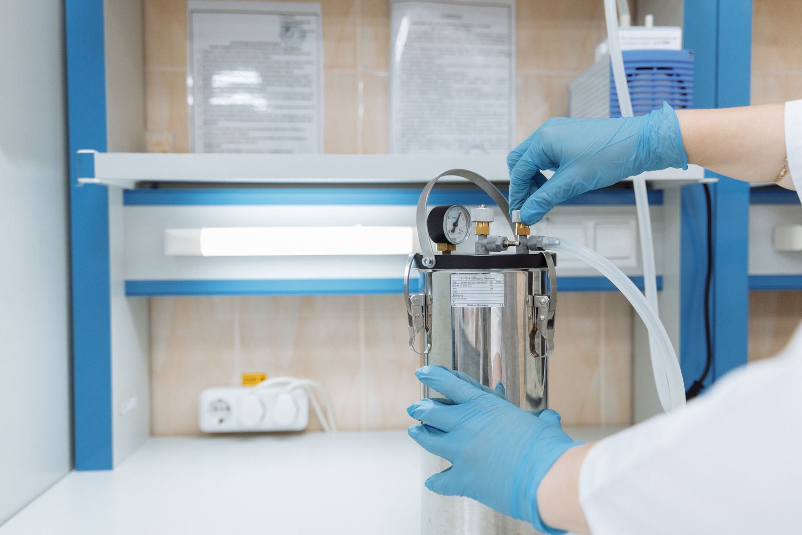
At a shift issue desk, a portable gas detector test result prints out. The overall operation has finished, but one channel shows a failure. If the person responsible reads “test complete” as “ready for use,” an instrument with an identified problem may reach the next worker.
A portable gas detector bump test exposes sensors to suitable test gas to verify detection and alarm function. Its purpose differs from calibration that adjusts accuracy. Sites must establish channel-specific records and a workflow preventing issue of failed instruments alongside the test method itself.
1. Self-diagnostics and bump tests check different things
Self-diagnostics check electronic circuits and alarm indications, but whether they replace testing with actual gas is a separate issue. A bump test checks gas entry and sensor and alarm functions. An accuracy check is needed to determine how closely the reading matches the reference concentration. OSHA distinctions between functional checks and calibration
Use separate checklist fields for “power normal” and “gas response normal,” because the first can pass while the second fails. Record responsibility and results for both so that a sound during boot does not lead to skipping test gas.
Shared instruments sitting in a charging dock can be easier to overlook than regularly used personal devices. If the previous user's check record is not connected to the serial number being issued now, “someone probably checked it” becomes an assumption. Establish a step in which issue personnel compare the displayed instrument ID with the record.
2. Record functional checks, accuracy checks and calibration separately
The table below provides operational distinctions to avoid confusing procedures. If menu names differ, first check definitions in the manufacturer manual.
Procedure | Question addressed | Result to retain | Consequence of confusion |
|---|---|---|---|
Self-diagnostics | Are power and internal diagnostics normal? | Error codes and alarm indications | Mistaking this for verification of sensor gas response |
Bump test | Does it respond to gas and activate alarms? | Pass/fail for each channel | Mistaking this for verified accuracy figures |
Accuracy check | Is the indication within tolerance relative to reference concentration? | Reference, reading and applicable tolerance | Mistaking this for completed adjustment |
Calibration and necessary adjustment | Was the reference relationship checked and sensitivity or other parameters corrected? | Before/after results and procedure used | Mistaking this for a permanent replacement for pre-use functional checks |
“Calibration” can be used differently in metrology documents and instrument menus. If running a bump test automatically leads to calibration, check the final record to see which stages occurred. Retain a change history if settings were changed during the test.
3. Match test conditions before starting
Check model, installed sensors, test gas components and concentrations, gas supply parts, test duration and acceptance criteria together. Correct gas concentration does not suffice if it fails to reach the channel or a different adapter changes the test. Do not judge compatibility from packaging that says “for four gases.”
Manufacturer Industrial Scientific distinguishes bump-test and calibration purposes and recommended frequencies by sensor operating configuration. Compare current installed configuration with its manual rather than applying one online procedure to every model. Manufacturer testing procedure guidance
The responsible person can post cylinder numbers, expiration dates and supply component models beside the test station. If calibration and bump-only gases are stored together, separate and label their purposes. Continue with checking calibration gas for gas and supply component selection.
Provide a safe location and discharge conditions when applying gas, following substance safety information and manufacturer instructions. Unverified flammable substances, lighter gas and vehicle exhaust cannot replace specified test gas. Avoid using hazardous workplace air as test gas too.
4. An execution sequence that checks every channel and alarm
Follow model instructions for actual button operations, and include this verification flow in the site procedure. Do not fix common numbers or times for all instruments.
Confirm instrument serial number and user, and check for previous failure or servicing status.
In a safe test location, inspect exterior, gas inlet and power condition.
Confirm test gas and supply parts match installed sensors.
Apply gas using the manual's test mode and supply method.
Observe each channel response and required alarm types, and record instrument judgments.
Complete test termination, gas removal and return procedures, then mark use status.
Hearing one alarm is different from every target channel passing. At a noisy issue point, even whether the sound was heard can be unclear. Provide an observable test environment and separate channel-specific judgments from visual and vibration alarm checks.
Review records even with docking stations. Check that insertion did not end in charging mode only, gas was not assigned to the wrong port, and neither overall nor partial channel failures occurred. Do not treat an automatic device's “complete” and “pass” as equivalent.
5. After failure, separate the instrument before retesting
After a failed bump test, first remove the instrument from usable stock and assign a replacement. Repeating tests and retaining only one eventual pass makes the initial failure difficult to trace. Preserve initial results and retest conditions together.
ISEA discusses functional verification and the need for follow-up after failure. Operators should decide calibration or service needs under manufacturer instructions and must not redeploy without evidence that the cause has been resolved. ISEA statement on validation of portable gas monitor operation
The following intake form distinguishes possible failure causes; it does not instruct field disassembly or repair.
Observation | Records or conditions to check | Information to hand over |
|---|---|---|
No response on all channels | Cylinder, supply connections and actual test mode | Test configuration photo and error code |
One channel fails | Sensor configuration and suitability of its test component | Channel, failure time and prior history |
Response but insufficient alarms | Alarm settings and test acceptance items | Settings and results for each alarm type |
Repeated failure after adjustment | Before/after results and service history | Stop-use label and service request |
When repeated failures affect one instrument, examine that instrument; when many fail together, also review common test conditions. This helps organize investigation, but multiple failures do not immediately prove test gas is at fault.
6. Hypothetical example: issuing ten shared instruments in the morning
The following hypothetical case explains a workflow. It is not a real customer or product performance example. A maintenance team checks ten shared detectors before work and finds a failed toxic gas channel on one unit.
The responsible person labels it “inspection failed—do not use” and issues a spare. After checking gas configuration and connections, they route it through the specified calibration and servicing procedure. The issue sheet records the failed and replacement instrument IDs side by side, allowing each worker's instrument to be traced.
The key is that they do not keep testing the failed unit merely to meet issue time. If spares are insufficient, contact the person responsible for adjusting the work plan. Designate return approval authority beforehand so checking personnel do not independently overturn a failure.
A record form can include “test date/time / instrument serial number / user / cylinder number and expiration / test procedure version / channel results / alarm results / failure actions / return approver.” These items make conditions easier to reconstruct than one signature field. For schedule design, also read operating criteria for calibration intervals.
Action checklist
[ ] Compare the instrument serial number with issue records.
[ ] Obtain a test procedure matching current sensors.
[ ] Confirm test gas components, concentrations, purpose and expiration.
[ ] Check supply parts and gas connections.
[ ] Record each channel result and required alarm response.
[ ] Mark failed instruments out of service and assign replacements.
[ ] Preserve initial failures and follow-up records together.
[ ] Confirm return decision authority and evidence after service.
Conclusion
The practical value of a bump test is checking gas response and alarms before use and preventing failed instruments from reaching the field. Power-on self-diagnostics, accuracy checks and calibration require separate records.
Connecting gas application with issue, isolation, service and return procedures puts results into actual equipment operation. Records linking instrument IDs with channel results support the next decision better than one pass stamp.
Sources
OSHA, Calibrating and Testing Direct-Reading Monitors, SHIB 11-26-2024: US advisory safety guidance, not a statutory interval in Korea.
Industrial Scientific, Calibration and Bump Testing Procedures: manufacturer guidance by instrument and sensor configuration.
ISEA, Statement on Validation of Operation for Direct Reading Portable Gas Monitors: basic principles of functional verification and follow-up.