
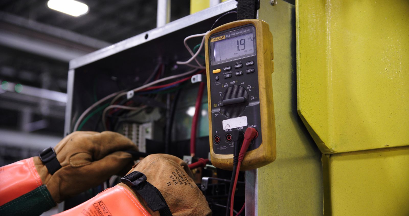
The workplace smells different from usual, yet the detector reads 0. A user may struggle to decide whether the instrument is wrong or there is merely an odor. Entering on the strength of one number or resetting zero at this point can erase evidence of causes that need checking.
A portable gas detector reading 0 means that the particular channel on that instrument currently displays 0 under those conditions. It is not proof that all hazardous gases are absent. First check whether a sensor measures the target gas, whether air reaches it, whether the instrument is operating normally, and its test history. Do not remain in a suspect atmosphere to investigate or adjust zero in potentially contaminated air.
Information missing from the number 0
Installed sensors and enabled channels determine what a gas detector measures. Even a configuration displaying oxygen, combustible gas, carbon monoxide and hydrogen sulfide does not check every other toxic gas and vapor in the same way. Check the actual sensor list before relying on nicknames or the label “multi-gas.”
For example, carbon monoxide (CO) and carbon dioxide (CO2) have similar names but are different measurement targets. Do not use 0 on a CO channel as evidence of CO2 absence. Determine required targets from site substance lists, process changes and safety data sheets, then compare them with the instrument configuration.
Performance also involves range, response time, environmental influences and interference. The US National Institute for Occupational Safety and Health (NIOSH) addresses these separately in direct-reading monitor evaluation. Interpretation of displayed numbers must therefore connect to what a sensor was evaluated to measure and under what conditions. NIOSH direct-reading monitor evaluation report
Display behavior may hide small changes
0 is affected by screen resolution and display rules. Display resolution is the increment the screen distinguishes; it differs from detection capability and accuracy. An integer display alone does not establish that smaller concentrations do not exist.
Some models suppress small fluctuations around zero. The Dräger X-am 3500/8000 technical manual describes this as the capture range. Verify its presence and range for the actual model, sensor and settings; do not use it to infer the conditions under which another product displays 0. Dräger technical manual: terms and settings
Disabling a display feature does not automatically improve safety. Changing settings without investigating the cause alters the basis for comparing existing alarm operation and records. If needed, a trained authorized person should review manufacturer instructions and site measurement objectives, make the change and retain its history.
Check sensor faults separately from air-entry problems
Even a working sensor may fail to represent surrounding air if its inlet is covered. For diffusion instruments, check whether clothing, protective equipment or contamination covers sensor inlets. For pumped instruments, also check hoses, probes, filters and connections. Inspect in a safe location; do not pierce inlets with needles or clean with unapproved compressed air.
A functional check of gas arrival differs in purpose from calibration checking accurate concentration readings. OSHA describes a bump test as a qualitative check of gas access and alarm function, distinct from accuracy measurement. A powered screen or passed self-test must not be treated as equivalent to verified test-gas response. OSHA calibration and testing guidance
If alarms, equipment errors or worker symptoms are already present, implement exit and reporting procedures before classifying causes. Smell cannot be the sole means of establishing either presence or absence. Workers must not be asked to compare a detector reading of 0 with an odor through bodily exposure.
Attach a 0-display checklist to measurement records
This table is an internal operating tool organizing the information needed to answer “why 0?” It is neither a site-safety declaration table nor a statutory form. Use it to decide additional checks when items remain unverified.
Question | Documents or conditions to verify | Action if unverified |
|---|---|---|
Does it measure the target gas? | Installed sensor names, part numbers and channel settings | Review suitable measurement methods |
Is normal measurement active? | Warm-up, errors, disabled channels and maintenance mode | Hold judgment until normal status is verified |
Does air reach the sensors? | Exposed inlets, filters, hoses and pump tests | Check sampling system and remeasure |
Has response to that gas been checked? | Functional-check date, result and test configuration | Test under manufacturer procedure |
Are conditions for a display of 0 known? | Units, resolution and display suppression settings | Compare manual and settings history |
Are place and time appropriate? | Location, depth, work stage and waiting time | Revise measurement plan |
Link instrument numbers with supporting record numbers instead of writing only “normal,” so the next shift can verify the same facts. With several instruments, compare serial numbers to prevent attaching another identical-looking instrument’s test result. Interpreting 0 requires traceable measurement conditions as well as concentration values.
Recorders can set the verification order even before knowing the cause. If a new process substance list does not match installed sensors, first review measurement suitability. If the sensor matches but hose condition is unverified, check the sampling system before remeasurement. Classifying both as sensor failure may lead to unnecessary replacement while leaving the real problem unresolved. Add owners and completion times to each checklist item so the next shift can inherit unfinished checks.
Hypothetical example: a record with all four channels at 0
This is a hypothetical review, not actual site results. A maintenance team records combustible gas, CO, hydrogen sulfide and oxygen all as 0. The original photograph shows that the oxygen channel was disabled; the recorder filled the empty field with 0.
Here, “oxygen 0” is not an actual measurement. One number alone cannot distinguish an actual oxygen concentration of 0, an inactive sensor and omitted entry. Preserve the original, correct the disabled channel to “not measured,” then repeat the measurement plan with an instrument equipped with the necessary sensors.
This example also does not mean that an oxygen sensor’s normal-air reference value is a universal safety criterion for every location. Check gas-specific units, criteria and differences in measurement targets together. A rule against converting absent-sensor blanks, communication gaps and error displays into numeric 0 can itself reduce major interpretation errors.
Do not erase uncertainty by zero adjustment
Zero adjustment sets an instrument’s reference. Forcing a display of 0 in potentially contaminated target air risks making that contamination the reference. A pleasingly lower number does not mean the cause was resolved.
Do not arbitrarily zero an instrument because it keeps showing 0 or, conversely, a small nonzero reading. Users should secure a safe location and check status and test history; the need for zero adjustment must be judged using appropriate clean conditions, zero gas and model procedures. Reviewing zero adjustment and clean-air verification helps prevent initial reference errors.
A normal response in retesting does not authorize immediate re-entry to the suspect location. Equipment return to service and workplace safety reassessment are separate decisions. Site approval procedures such as ventilation, isolation, remeasurement and work permits must be complete; do not retroactively relabel previous 0 readings as normal.
Action checklist
[ ] Verify the channel and unit displaying 0 on the original screen.
[ ] Compare target substances with installed sensors and active channels.
[ ] Distinguish warm-up, errors and disabled status from normal measurement.
[ ] Check covered inlets and sampling problems in a safe location.
[ ] Distinguish test-gas functional-check results from accuracy checks.
[ ] Verify model-specific resolution and display suppression applicability.
[ ] Do not enter unmeasured, missing or error data as numeric 0.
[ ] Do not arbitrarily adjust zero in potentially contaminated air.
Conclusion
Interpret a portable gas detector reading 0 only after checking the target measured, air-entry conditions, normal operation and display rules. 0 alone cannot prove the absence of every gas or workplace safety.
When response differs from expectations, prioritize site exit, reporting and measurement-validity review. Checking pump flow errors alongside under-reading due to cross-sensitivity helps separate instrument conditions from air conditions.
Sources
NIOSH, Components for Evaluation of Direct-Reading Monitors for Gases and Vapors — Evaluation factors including range, environment and interference.
Dräger, X-am 3500/8000 Technical Manual, Edition 11 — Distinguishes capture range and normal measurement status for the specified models.
US OSHA, Calibrating and Testing Direct-Reading Portable Gas Monitors — Distinguishes functional checks and accuracy verification. Does not replace Korean statutory requirements.